

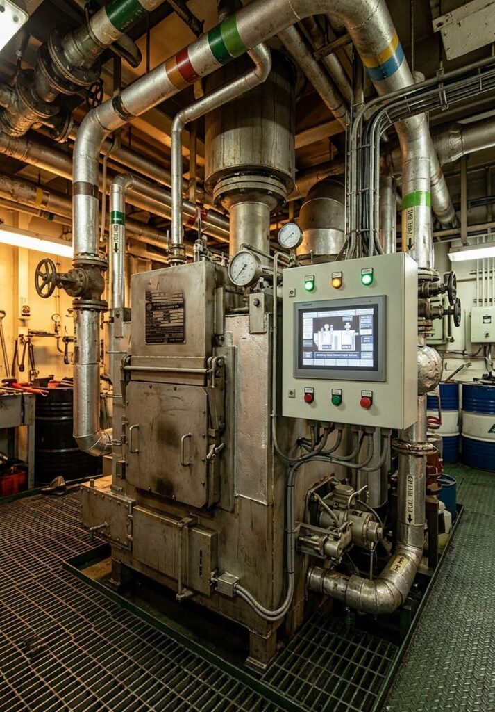
A marine incinerator is a vital piece of shipboard equipment designed for the thermal destruction and disposal of solid waste and waste oil (sludge) directly on board a vessel. Waste disposal at sea is strictly regulated by the International Convention for the Prevention of Pollution from Ships (MARPOL 73/78, Annex V) and IMO standards (MEPC 76(40)).
The use of modern incinerators allows vessels to comply with international environmental regulations, significantly reduce the volume of stored waste on board, and minimize waste disposal fees at port reception facilities.
What is a Marine Incinerator Used For?
During normal ship operations, various types of waste are continuously generated. According to IMO requirements, marine incinerators are built to burn two primary waste categories:
- Liquid Waste (Waste Oil / W.O. / Sludge):
- Heavy fuel oil sludge and waste oil
- Oily sludge from purifiers and drain tanks
- Waste lubricating oil and bilge water emulsions
- Solid Waste (Solid Waste Class II):
- Domestic rubbish and food waste
- Rags, paper, cardboard, textiles, and permitted plastics
Technical Specifications and Standards
Modern multi-chamber marine incinerators are designed as compact units certified by leading classification societies (such as ABS, USCG, MED).
More information on Slide Fuel Valves: Principle, Advantages, IMO NOx Compliance
| Parameter | Value / Characteristic |
| Calorific Capacity | up to $500,000\text{ kcal/h}$ ($581\text{ kW}$) |
| Solid Waste Capacity | up to $100\text{ kg/h}$ |
| Waste Oil (Sludge) Capacity | up to $59\text{ kg/h}$ |
| Flue Gas Retention Time | $1\text{ second}$ |
| Flue Gas Temperature | approx. $350^\circ\text{C}$ |
| Pilot / Preheating Fuel | Marine Diesel Oil (M.D.O.) |
| Compressed Air Pressure | $7\text{ kg/cm}^2$ |
| Power Supply | AC 440V (60 Hz, 3-Phase) / AC 220V (1-Phase) |
Main Components and Construction Elements
A marine incinerator consists of an integrated set of systems designed to ensure complete combustion and operational safety:
- Primary and Secondary Combustion Chambers: Multi-chamber design ensures gradual heating, thorough burning, and secondary re-burning of exhaust gases.
- Diesel Oil (D.O.) Burners: A primary chamber burner and a secondary chamber burner to achieve and maintain required combustion temperatures.
- Waste Oil (W.O.) Burner: Equipped with a dosing pump for regulated feeding of atomized oil sludge.
- Air Blower: Supplies combustion air, cooling air, and airflow for the flue gas air ejector.
- Non-Fire Back Sluice (Loading Door): A double-door interlocked system that prevents blowback of flames and controls air ingress during solid waste feeding.
- Control Panel (CP1 / PLC): Features an automated control system, flame safety monitors, and high-temperature alarms.
- Thermocouples: High-accuracy temperature sensors located in the primary chamber, secondary chamber, and flue gas duct.
Working Principle of a Marine Incinerator
The waste incineration process follows a structured sequence controlled automatically by safety logic.
[Pre-purging] ➔ [Pre-heating] ➔ [Waste Feeding & Incineration] ➔ [Cooling & Shutdown]
1. Preparation and Pre-purging
Before ignition, the air blower runs a pre-purge cycle for a minimum of 60 seconds to clear any unburnt flammable gases from the combustion chambers, eliminating explosion risks.
2. Pre-heating Stage
To achieve efficient waste combustion, the incinerator must reach its minimal operating temperature. The secondary chamber diesel oil burner ignites first, raising the temperature in the secondary chamber to $650^\circ\text{C}$–$700^\circ\text{C}$ over approximately 30 minutes.
3. Solid Waste Incineration Mode (MD2)
Once the secondary chamber reaches $650^\circ\text{C}$, the primary chamber D.O. burner ignites the solid waste loaded inside.
- Sluice Operation: Pressing the waste loading button automatically unlocks the outer feeding door while keeping the inner door locked. Once waste is inserted and the outer door closes, the inner door opens to drop the waste into the primary chamber. This double-barrier system prevents flame blowback and excess draft air ingress.When the primary chamber reaches $750^\circ\text{C}$, the secondary burner automatically stops to conserve fuel. If the temperature drops below $670^\circ\text{C}$, it automatically reignites.
4. Liquid Waste / Sludge Incineration Mode (MD1)
Burning waste oil requires sustained high temperatures between $850^\circ\text{C}$ and $950^\circ\text{C}$. Sludge is preheated, atomized, and injected via the W.O. burner metering pump. High temperatures in the secondary chamber ensure complete re-burning of soot particles and volatile organic compounds before exhaust gas discharge.
5. Cooling and Automatic Shutdown
After waste feeding stops and burners shut down, the draft fan continues running in a cooling loop. The automated cooling program keeps fans running until the chamber temperature drops below $100^\circ\text{C}$.
The working principle of a marine incinerator relies on thermal destruction of solid garbage and oil sludge at controlled temperatures up to $950^\circ\text{C}$. Proper operation of shipboard incinerators ensures total environmental compliance with MARPOL regulations and guarantees safe waste management at sea.