
Modern marine power plants primarily operate on heavy fuel oils (HFO with viscosities up to $700\text{ cSt}$). During bunkering and long-term storage on board, fuel inevitably becomes contaminated with water and solids, such as sand, dust, and rust scale.
Using fuel with high concentrations of foreign impurities is extremely hazardous to engine components. It causes rapid clogging of fuel injectors, severe abrasive wear on plunger pairs of high-pressure fuel injection pumps (HPFP), and accelerated wear on cylinder liners and piston rings of main and auxiliary engines.
To ensure reliable and uninterrupted operation of marine diesel engines, a comprehensive fuel conditioning and purification system is required.
More information on CentriShoot & CentriLock: The Future of Separator Maintenance
Primary Methods of Heavy Fuel Purification on Ships
Shipboard fuel treatment relies on a three-stage purification system:
- Gravity Settling in Settling Tanks: Fuel is held in a settling tank for 20–22 hours. During this period, heavy particles and free water settle to the bottom by gravity, where they are periodically drained via a sludge drain valve.
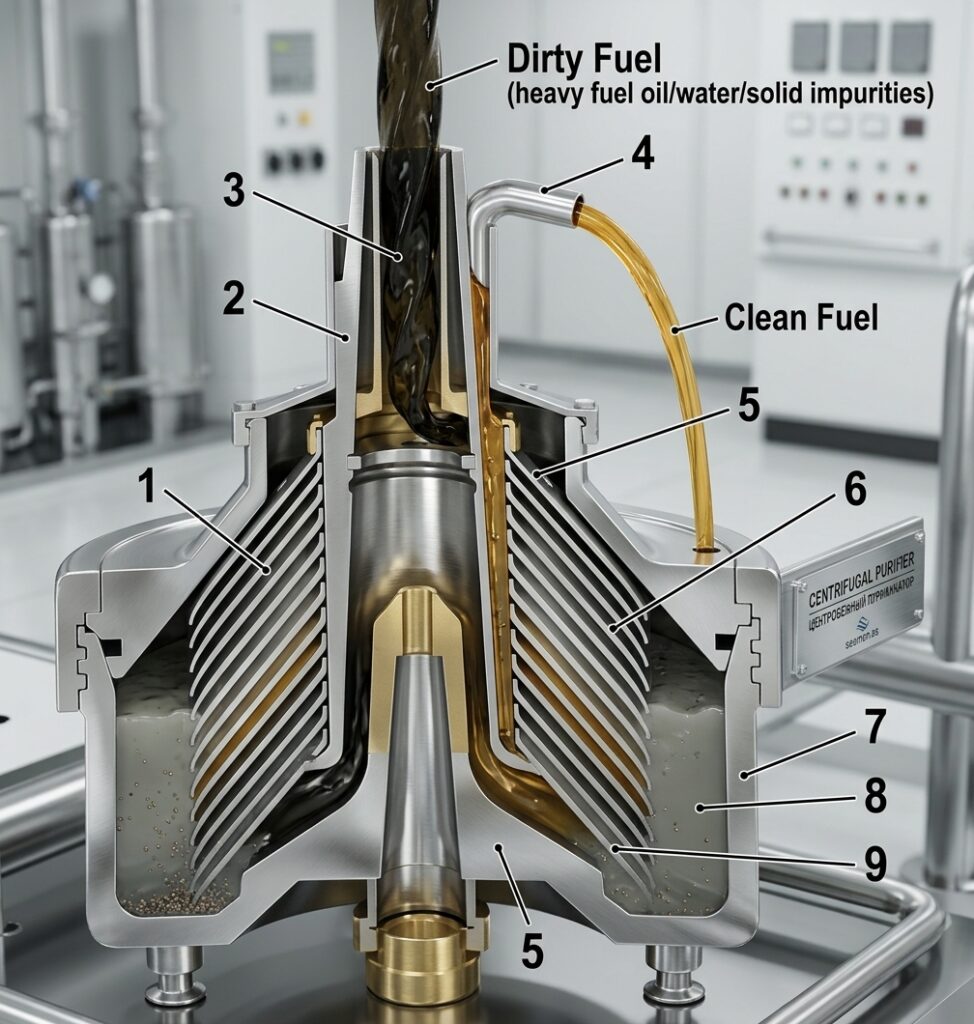
- Centrifugal Separation (Most Effective Method): A dynamic process that separates water, fuel, and solid impurities based on density differences under high centrifugal forces generated inside a rotating bowl.
- Filtration: The final stage. Separated fuel from the service tank is pressurized to $0.4\text{–}0.6\text{ MPa}$ by a booster pump and passed through fine filters before being delivered to the engine’s fuel injection pumps.
Working Principle of Disc-Type Centrifugal Separators
The core component of the fuel treatment system is the centrifugal disc separator. Depending on the operational goal and fuel condition, the separator bowl can be configured in two main modes: Clarification (removal of solids) and Purification (removal of water and solids).
1. Clarification Mode (Clarifier)
Clarification is used when the fuel contains predominantly solid impurities and minimal water content.
- Operating Process: Unpurified fuel enters the rotating bowl through the central distributor pipe. Flowing downward, it is directed toward the bowl periphery and passes upward through narrow gaps between conical discs.
- Separation of Solids: Under centrifugal force, heavy particles are thrown against the inner wall of the bowl, settling in the sludge space and on the conical disc surfaces. The cleaned fuel moves toward the center and exits through the upper clarifier outlet.
- Limitations: If water is present in the fuel, it precipitates along with the sludge and gradually fills the sludge space. The accumulated water layerEventually blocks the entrance to the inter-disc space. As a result, raw fuel fills the central distributor pipe and overflows through the overflow pipe, signaling an immediate need to stop and clean the separator.
2. Purification Mode (Purifier)
To continuously separate water from wet fuel, the bowl is configured as a purifier.
- Design Features: A separating disc, a regulating disc (gravity disc) on the water outlet, and a disc stack with distributor holes aligned vertically to create channels for fluid distribution are installed inside the bowl.
- Water Seal (Hydrosheal): Before feeding fuel into the rotating bowl, seal water must be added to form a hydraulic seal. This prevents heavy fuel from escaping through the water outlet.
- Phase Separation: Once the water seal is established, fuel feed begins. Fuel passes down the central distributor pipe into the disc stack channels and spreads through the inter-disc spaces.
- Water (the heavier phase) is thrown to the bowl periphery, merges with the water seal, and continuously discharges through the gravity disc outlet.
- Cleaned Fuel (the lighter phase) is displaced toward the bowl axis and exits via the outlet passage above the separating disc.
Interface (Neutral Layer) and Gravity Disc Selection
During steady-state purification, an interface layer (also referred to as the neutral layer) is formed—an imaginary cylindrical surface dividing the water and fuel phases.
For maximum separation efficiency, this interface must be positioned directly within the line of the vertical distributor holes of the disc stack. The position of the interface is governed by the hydrodynamic balance of three streams (incoming fuel, outgoing clean fuel, and discharged water) and is adjusted using an interchangeable regulating disc (gravity disc).
Separators are supplied with a set of gravity discs featuring various inner hole diameters ($D_{g}$).
Common Selection Errors and Operational Signs:
- Gravity Disc Hole Diameter Too Small:
- The interface shifts inward toward the bowl center.
- Water covers part of the effective disc area and leaks into the clean fuel line.
- Operational Sign: Fogging or moisture droplets visible in the clean fuel sight glass.
- Action: Stop the separator and install a gravity disc with a larger hole diameter.
- Gravity Disc Hole Diameter Too Large:
- The interface shifts outward toward the bowl periphery, extending past the edge of the separating disc.
- The water seal breaks, causing raw fuel to escape together with the separated water.
- Operational Sign: Fuel appearing in the sludge/water outlet sight glass.
- Action: Immediately stop the separator and install a gravity disc with a smaller hole diameter.
Important: Correct gravity disc selection is performed by marine engineers using manufacturer nomograms and tables based on fuel density, separation temperature, and water content.
Paring Discs (Centripetal Pumps)
To discharge purified fuel and separated water from the spinning bowl under pressure, paring discs (centripetal pumps) are utilized.
- Operating Principle: The paring disc is stationarily mounted inside the bowl, while the liquid layer rotates around it at high speed along with the bowl.
- As the rotating liquid ring impinges on the stationary channels of the paring disc, its kinetic energy is converted into static pressure.
- The liquid flows from the outer periphery of the disc inward toward the center (operating as a centripetal pump, opposite to a standard centrifugal pump).
- Paring discs can generate discharge pressures up to $0.25\text{ MPa}$, eliminating the need for additional discharge pumps downstream.
Kinematic Scheme and Drive Mechanism
The high operating speeds (6,000 to 10,000 RPM) of the separator bowl are achieved through a dedicated gear transmission:
- Drive Assembly: The electric motor and separator frame are mounted on a common baseplate. Torque is transmitted from the motor to the horizontal shaft through a friction clutch, enabling smooth acceleration and protecting the motor from starting overloads.
- Worm Gear Pair: A worm gear on the horizontal shaft meshes with a worm on the vertical spindle, stepping up the speed for the vertical shaft.
- Spindle Bearings:
- Upper Bearing: Houses a radial ball bearing supported by radial spring dampers to absorb vibrations and ensure dynamic balancing.
- Lower Bearing: Absorbs axial and radial loads, utilizing angular contact ball bearings.
- Bowl and Hood: The bowl is fitted onto the tapered upper end of the vertical spindle, enclosed by a protective frame hood equipped with sight glasses for visual monitoring.
- Auxiliary Pumps: Gear-type feed and discharge pumps may be driven directly from the horizontal shaft via a flexible coupling.
Major Manufacturers of Marine Separators
The global commercial fleet predominantly utilizes centrifugal separators from industry-leading manufacturers:
- Alfa Laval (MAPX, FOPX, S, and P-separator series);
- GEA Westfalia (OSD, OSE series);
- Titan;
- Sharples.
Mastering the principles of centrifugal phase separation and correct interface adjustment allows marine engineers to maintain optimal fuel cleanliness and extend the service life of main and auxiliary engine components.